
Simulating Your ARC Rocket in OpenRocket: From Design to Predicted Altitude
Use OpenRocket to design and tune an American Rocketry Challenge rocket — build the model, set mass and the payload, check stability margin, and simulate apogee and flight time before you build.
The American Rocketry Challenge is won on precision. Every season the official rules specify a target altitude and a required flight duration window, and your score depends on how accurately your rocket hits both numbers. Those targets change from season to season, so before you commit to a design, download the current rules from the official ARC website and note the exact altitude, duration window, and payload requirements for your competition year.
Simulation lets you iterate on the computer for free instead of burning motors. A single Estes motor costs a few dollars and requires a trip to the field. A change in OpenRocket costs nothing and takes thirty seconds. If you are new to the competition, the Getting Started with the American Rocketry Challenge guide explains the full season structure before you dive into the design workflow here.
What OpenRocket Is
OpenRocket is a free, open-source model-rocket flight simulator maintained by a community of rocketry engineers and hobbyists. You build a virtual rocket by adding components — nose cone, body tubes, fins, motor mount — and the software predicts:
- Apogee (maximum altitude)
- Time to apogee
- Optimum delay (how long after burnout the ejection charge should fire)
- Total flight time (from launch to landing)
- Stability margin (whether the rocket will fly straight)
- Descent rate (given your parachute diameter)
OpenRocket uses Barrowman equations for aerodynamic coefficient estimation and numerical integration for the flight trajectory. Its predictions are not perfect — real rockets face real air, and your motor's actual thrust curve differs slightly from the certified average — but they are accurate enough to guide design decisions before you cut a single piece of tube. The simulate-then-calibrate method, described at the end of this guide, closes the gap between prediction and reality.
You can download OpenRocket at openrocket.info. It runs on Windows, macOS, and Linux.
Building Your Rocket Model
Adding Components in Order
OpenRocket builds rockets from the nose back. Start a new design and add components in this sequence:
- Nose cone — select the shape (ogive, conical, parabolic) and enter the length and base diameter. Ogive nose cones are standard for ARC rockets because they balance drag and manufacturability.
- Body tube — enter the outer diameter, wall thickness, and length. If your rocket has two body sections separated by a coupler, add each tube separately.
- Fin set — add a trapezoidal or elliptical fin set and enter root chord, tip chord, span (fin height), and sweep angle. Fin geometry directly controls the center of pressure, so these numbers must match your actual fins. If you are printing your fins, read the 3D-printed fins guide for the dimensional considerations that affect stability simulation.
- Motor mount / inner tube — add an inner tube component inside the aft body tube and set its diameter and length to match your motor mount tube.
Entering Dimensions and Materials
For every component, set the material in the component editor. OpenRocket uses material density to calculate component mass automatically. Common choices: balsa or kraft paper for tube stock, PLA or ABS for printed parts, aluminum for metal hardware.
This is where the garbage-in-garbage-out rule applies most directly. If you leave components at OpenRocket's default material (often fiberglass when you are actually flying a cardboard tube), the predicted mass will be wrong, and a wrong mass produces a wrong apogee prediction. Measure your actual materials. If you have a piece of body tube, weigh it on a postal scale, divide by its volume, and compare to OpenRocket's material density. Use the "custom" material entry if the match is not close enough.
After you have entered all components, look at the "Rocket" panel on the right side of the screen. The total dry mass displayed there should be within a few grams of your actual airframe weighed on a scale. If it is off by ten or twenty grams, find the discrepant component and correct it.
Mass, the Payload, and Realistic Inputs
Adding Payload Mass
ARC rockets carry an egg as a live payload. Before you finalize your mass entries, confirm the exact payload and mass rules in the current official ARC rulebook — the egg specification and any additional payload requirements are stated there and they can change between seasons.
In OpenRocket, add a mass component inside the nose cone section (or wherever your egg compartment sits) and enter the mass of the egg plus its protection packaging. A raw egg is roughly 55–65 grams. If you are using a foam cradle, bubble wrap, or a printed egg holder, add those masses too. Weigh your actual egg compartment assembly.
Accounting for Everything Else
Most student simulations are optimistic because they under-enter mass. Here is the full list of mass items to include, each as a separate mass component placed at its approximate axial location in the rocket:
- Altimeter or flight computer — typically 15–30 grams depending on the model. Place it at the axial location of your electronics bay.
- Battery — weigh it.
- Parachute and shock cord — a 45 cm nylon parachute and elastic shock cord together typically run 30–50 grams.
- Recovery wadding or flame barrier — 5–10 grams.
- Epoxy fillets and adhesive — estimate 10–20 grams total depending on construction.
- Paint and finish — a full spray-painted airframe adds 10–20 grams depending on number of coats.
- Launch lug or rail button hardware — a few grams each, but they add up.
Adding all of these takes ten minutes in OpenRocket and can shift your predicted apogee by 30–80 feet depending on rocket size. That is the difference between a good score and a disqualifying altitude.
Once your model mass matches your scale-measured airframe to within five grams, you can trust the simulation's altitude and flight time outputs as a starting point.
Stability: CG, CP, and Margin
What CG and CP Mean
The center of gravity (CG) is the point at which the rocket balances. It is a function of mass distribution — add mass to the nose and CG moves forward; add mass to the tail and it moves aft. OpenRocket calculates CG automatically from all your component masses.
The center of pressure (CP) is the point at which aerodynamic forces act on the rocket. It depends entirely on geometry — fin area, nose cone shape, and body tube dimensions. OpenRocket calculates CP using the Barrowman equations. CP is always shown on the stability bar at the bottom of the design window.
The Stability Margin
Stability margin is defined as:
Stability margin (calibers) = distance from CG to CP / body tube outer diameter
For a rocket to fly straight, CG must be forward of CP. If CG is behind CP, the rocket is aerodynamically unstable and will rotate nose-aft immediately after leaving the rod. A commonly cited safe range for sport and competition model rockets is 1.0 to 2.0 calibers. Below 1.0 caliber, small disturbances can drive the rocket off course. Above 2.5 to 3.0 calibers, the rocket becomes overly stable and will weathercock — turn into the wind — significantly, which hurts altitude accuracy on windy days.
OpenRocket displays CG and CP as colored markers on a side-view diagram of your rocket. The stability margin is shown numerically next to the diagram. Watch it update in real time as you adjust fin dimensions or add mass components. A 1.5-caliber margin is a reasonable design target for most ARC rockets.
Practical Adjustments
If your margin is below 1.0 caliber, increase fin span, move fins further aft, or add a small nose weight. If your margin is above 2.5 calibers, reduce fin area or remove nose weight. Each adjustment takes seconds in the component editor. Make one change at a time and read the updated margin before making another.
Running a Simulation
With your model built and masses entered, select a motor. Go to the motor mount component, click "Select motor," and search by manufacturer and designation. ARC-eligible motors are listed in the current rules; confirm you are simulating an approved motor.
Set the launch conditions in the simulation settings:
- Launch rod or rail length — match your actual launch equipment. ARC competitions use a specific rod or rail; check your rules. A longer guide rod produces a higher velocity at the moment the rocket leaves the rod, which affects stability.
- Launch angle — leave at 0 degrees (vertical) for your baseline simulation.
- Wind speed — set it to zero for a calm-day baseline. Run a separate simulation at expected field wind conditions (5–10 mph) to see how much the predicted apogee drops and whether the rocket weathercocks significantly.
After clicking "Run simulation," open the results panel. You will see:
- Maximum altitude (apogee) — this is your primary tuning target.
- Time to apogee — important because ARC scores flight duration from launch to landing.
- Optimum delay — how many seconds after burnout the ejection charge should fire for the best altitude recovery deployment. Match your motor's ejection delay to this number as closely as the motor's available delay options allow.
- Total flight time — from launch to touchdown, given your parachute diameter.
If total flight time does not match the ARC duration target, adjust your parachute size. A larger parachute increases descent time. A smaller one decreases it. Rerun the simulation after each change.
Tuning to the Target Altitude and Duration
Once you have a baseline simulation, you are iterating to bring predicted apogee and predicted total flight time into the competition window defined by your current season's rules.
To raise apogee: reduce total mass (lighter paint, smaller parachute packing, trimming unused structure), reduce drag (smoother finish, smaller fin area), or switch to a higher-impulse motor.
To lower apogee: add nose weight, increase parachute size, or switch to a lower-impulse motor.
To adjust flight duration: parachute diameter is your primary lever. A larger canopy produces a slower descent and a longer flight time. A smaller canopy descends faster and shortens total time. Use OpenRocket's "Recovery" simulation output to target a descent rate of roughly 4–6 m/s for a typical ARC rocket.
OpenRocket includes an optimization feature (under the "Tools" menu) that will automatically search for the best combination of altitude and flight time given constraints you define. It is a useful check, but use it after you understand the manual tuning process — otherwise you will not know why the optimizer is making a given recommendation, and you will not be able to troubleshoot when the real flight does not match.
When selecting and changing motors, cross-reference the choosing a motor guide for ARC-specific motor certification requirements and the practical differences between motor classes that affect flight dynamics.
Calibrating the Model With Real Flight Data
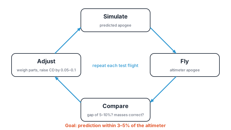
OpenRocket's predictions are a starting point. After your first real flight, compare the altimeter reading to the simulation's predicted apogee. A well-built model with accurate mass inputs will typically predict within 5–10% of actual altitude. If your altimeter reads 820 feet and OpenRocket predicted 900 feet, the simulation is running optimistic.
To calibrate:
- Open the simulation results and check whether your entered masses match the flown rocket (weigh everything after the flight).
- If masses match but the prediction is still high, increase the drag coefficient. In OpenRocket, this is the "CD" override in the simulation settings. Small increases in CD (0.05–0.1) can close a 5–10% gap.
- Rerun the simulation with the adjusted CD and verify that it matches the altimeter data from that flight.
A calibrated model is one where OpenRocket's predicted apogee matches your altimeter data from a real flight to within 3–5%. Once you have that calibration, predictions for future design changes are trustworthy.
For more detail on reading and interpreting altimeter data, and for a comparison of altimeters suited to ARC-class rockets, see the altimeter flight data guide.
Common Mistakes to Avoid
- Under-entering mass. Forgetting paint, epoxy fillets, and egg packaging is the most common reason student simulations predict altitudes 50–100 feet higher than actual flight. Weigh everything.
- Using default materials. OpenRocket defaults often do not match the tube stock and printed parts students actually use. Set materials manually for every structural component.
- Ignoring wind conditions. A zero-wind simulation on a day with 10 mph winds will predict a higher apogee than you actually achieve. Run simulations at realistic field conditions.
- Trusting the sim without a real-flight check. Even a well-entered model has error. Do not show up to qualification rounds without at least one calibration flight.
- Setting stability margin outside the 1–2 caliber range. Below 1.0 caliber risks unstable flight. Above 2.5 calibers introduces significant weathercocking on windy days, which costs altitude.
- Choosing a motor delay without checking the optimum delay output. OpenRocket tells you the optimum delay time. If your motor's available delays are all longer than the optimum, apogee deployment will occur on the descent — hurting recovery reliability.
- Changing multiple parameters between flights. Changing fin geometry, motor, and mass at the same time makes it impossible to know which variable drove the change in altitude. Change one thing per flight cycle.
Where to Go From Here
Start your OpenRocket model early in the season — before you order materials, not after. A few hours in the simulator will tell you whether your body tube diameter is sensible for your target altitude, whether your fin geometry provides adequate margin, and whether your parachute will produce a legal flight time. Discovering a design flaw on the computer is far cheaper than discovering it at the launch field.
If you want structured coaching on simulation workflow, motor selection, stability tuning, and competition-day preparation, explore our ARC coaching classes — SEALS Academy coaches ARC-track students competing in Orange County and across Southern California.